A Combinational circuit is a series and parallel circuit combined together. Combinational circuits are fundamental building blocks in electronics, forming the backbone of various devices we use in our everyday lives. In this guide, we'll take you through the step-by-step process of creating series and parallel combinational circuits using both MATLAB simulation and practical breadboard implementation. By the end, you'll have a deep understanding of these circuits and how they function in real-world scenarios.
Introduction
Combinational circuits are integral to modern electronics, enabling the creation of complex systems that perform various tasks. These circuits are constructed using different combinations of components, including resistors, capacitors, and diodes. Our goal in this guide is to provide you with a comprehensive understanding of series and parallel combinational circuits through MATLAB simulation and hands-on breadboard construction.
Section 1: Understanding Series and Parallel Combinational Circuits
Before we delve into the practical aspects, let's establish a solid foundation by understanding the key concepts of series and parallel combinational circuits.
Series circuits are characterized by components connected end-to-end, creating a single pathway for current flow. In contrast, parallel circuits have components connected across common points, allowing multiple pathways for current to flow. Each configuration has unique implications for voltage, current, and overall circuit behavior.
To learn more about the series and parallel circuit and how to build them, read our tutorial Step-by-Step Guide to Building Series and Parallel Circuits with MATLAB Simulation
Section 2: MATLAB Simulation of Series and Parallel Combinational Circuits
 |
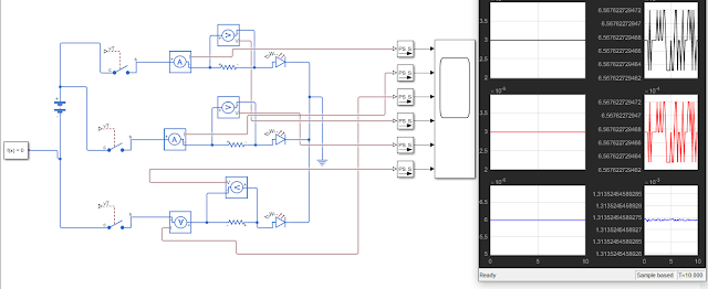
| MATLAB Simulation of a combinational Circuit |
MATLAB is a powerful tool for simulating and analyzing electronic circuits. Let's explore how to use MATLAB for simulating both series and parallel combinational circuits. The summary of the steps to follow are listed below
1. Install Necessary Toolboxes:
Begin by ensuring you have the required toolboxes for circuit simulation. MATLAB's Simulink and Simscape Electronics libraries are essential for this purpose. Hence download the MATLAB software from the website MATLAB-Download
2. Circuit Creation and Component Placement:
Open MATLAB and create a new project for your circuit simulation. To create a new project you need to open the Simulink tab on the MATLAB home page. Use Simulink's circuit editor to lay out the components of your chosen circuit configuration.
3. Component Values and Connections:
Assign appropriate values to resistors and other components. Establish connections between components by connecting nodes with wires.
4. Running the Simulation:
Once your circuit is set up, initiate the simulation to observe how voltage and current behave across the circuit.
The video below shows a visual walkthrough of the MATLAB simulation process summarized above.
Section 3: Practical Breadboard Implementation
While simulations provide valuable insights, hands-on experience is equally important. Let's move from the virtual world to the physical realm by building these circuits on a breadboard.
1. Gather Components:
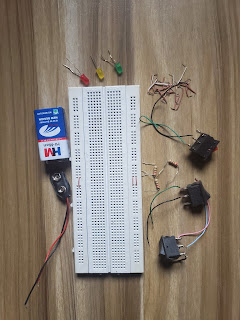
The following materials are required to carryout the hands on practical of a combinational circuit
- Breadboard
- 9V battery
- battery connector
- 220 ohms resistor (3)
- SPST switch (3)
- LED (1 red, 1 yellow, 1 green)
- Jumper wires
 |
| Materials required |
2. Component Placement:
Follow the steps and images below to place the components and jumper wires on the breadboard
Step #1- Place the connector on the breadboard with the red wire to one column of the breadboard and the black wire to another column on the breadboard as shown in the image below.
Step #2- Connect the switches to the breadboard, with the first pin connected to the positive column of the connector and the second pin connected to any row in the breadboard as shown in the image below.
Step #3- Place the first lead of each resistor in same row with the second pin of the switch with the other resistor lead placed in opposite row as shown in the image below
Step #4- Add each LED to the circuit by connecting the positive lead to the resistor and the negative lead to the column of the connector black wire as shown in the image below. You can choose any LED color
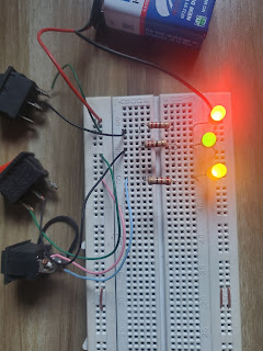
Step #5- Connect the 9V battery with the connector. If all the component are placed correctly, each LED will light up when the switch is turned on. The images below show the circuit response when different switches are turned on.
 |
| Only Switch one turned On |
 |
| Only Switch two turned On |
 |
| Only Switch three turned On |
 |
| All Switches turned On |
3. Verification:
Before applying power, double-check your connections to avoid potential mistakes. Once confirmed, power up the circuit and observe its behavior.
The Video Below Shows how the circuit Works.
Section 4: Troubleshooting and Tips
During both simulation and practical implementation, you might encounter challenges. Here are some troubleshooting tips to help you overcome common issues:
- Unexpected Simulation Results: Verify component values and connections in your MATLAB simulation setup.
- Non-Functional Breadboard Circuit: Inspect connections and ensure components are placed correctly.
- Fluctuating Readings: Check for loose wires or faulty components that could lead to unstable readings.
Remember, persistence and hands-on practice are key to mastering circuit construction and analysis.
Conclusion
Congratulations! You've journeyed through the realm of combinational circuits, from MATLAB simulation to breadboard implementation. This guide has equipped you with the knowledge and skills needed to design and build series and parallel circuits, both virtually and physically. As you explore further, you'll discover the immense potential of combinational circuits in powering our technological world.
Additional Resources
- [Recommended Reading: Step-by-Step Guide to Building Series and Parallel Circuits with MATLAB Simulation]
- [Advanced Circuit Design Tutorials]


