In the world of electronics, rectifiers play a crucial role in converting alternating current (AC) into direct current (DC). Among the various types of rectifiers, the half-wave rectifier stands out for its simplicity and efficiency in certain applications. In this blog post, we will explore what a half-wave rectifier is, its practical uses, and guide you through the process of simulating a half-wave rectifier circuit using MATLAB.
What Is a Rectifier?
Before diving into half-wave rectifiers, let's briefly understand the concept of a rectifier. A rectifier is an electronic device that converts AC voltage (alternating voltage) into DC voltage (direct voltage). This conversion is essential for many electronic devices and power supplies, as most electronic components require DC power to function correctly.
What Is a Half-Wave Rectifier?
 |
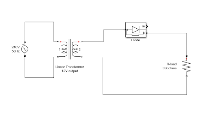
| Half-wave rectifier circuit |
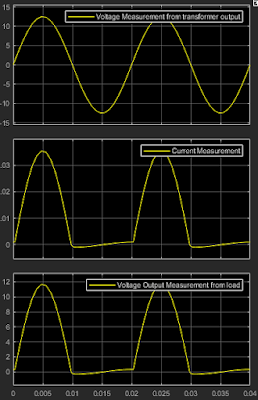
A half-wave rectifier is a type of rectifier that allows only half of the input AC cycle to pass through while blocking the other half. In other words, it converts the positive half of the AC input waveform into DC, effectively removing the negative voltage portion. The diode in the circuit allows current flow in one direction hence during the positive half cycle, the diode is forward biased thereby allowing current to flow and during the negative half cycle, the diode is reversed biased thereby blocking the flow of current. This results in a pulsating DC output that consists of only the positive half of the input waveform.
 |
| Half-wave rectifier input and output waveforms |
Compared to full-wave rectifiers, half-wave rectifiers are less efficient because they utilize only half of the available AC power. However, they are still widely used in applications where simplicity and cost-effectiveness are more critical than efficiency.
The Use of Half-Wave Rectifiers
Half-wave rectifiers find applications in various electronic circuits, including:
Battery Chargers:
Half-wave rectifiers are used in low-cost battery chargers for devices like flashlights and radios.
Signal Demodulation:
In radio receivers, half-wave rectifiers are used to demodulate amplitude-modulated (AM) signals.
Pulse Generation:
They can be used to generate pulse signals for timing and control purposes.
Voltage Reduction:
In some cases, half-wave rectifiers are used to reduce the peak voltage of AC signals.
Components of a Half-Wave Rectifier Circuit
To build a half-wave rectifier circuit, you'll need the following components:
- AC voltage source: Provides the input AC signal.
- Linear Transformer: Steps down or steps up the voltage as needed.
- Diode: Allows current to flow in one direction only, acting as the rectifying element.
- Current Sensor: Measures the current flowing through the circuit.
- Voltage Sensor: Measures the output voltage.
- Resistor (Load): Represents the device or load connected to the rectified output.
Half-Wave Rectifier Simulation Using MATLAB
 |
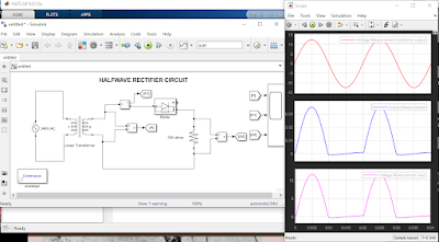
| Half-wave rectifier MATLAB simulation |
Now, let's explore how to simulate a half-wave rectifier circuit using MATLAB. MATLAB is a powerful tool for simulating and analyzing electronic circuits. Here is summary of the basic steps for designing and simulating the half-wave rectifier:
- Setting up the MATLAB Environment: Launch MATLAB and create a new script or Simulink model.
- Building the Circuit Model: Define the circuit components and their connections within MATLAB/Simulink.
- Defining Parameters and Components: Specify the parameters for the AC source, transformer, diode, and load resistor. Set initial conditions as needed.
- Running the Simulation: Execute the simulation and observe the output waveforms.
- Analyzing the Results: Use MATLAB's analysis tools to examine the rectified output, including voltage and current waveforms.
Video Demonstration
For the visual guide on how to simulate a half-wave rectifier circuit using MATLAB, watch the video below:
Conclusion
In this blog post, we've explored the world of half-wave rectifiers, their applications, and the essential components of a half-wave rectifier circuit. We've also provided a guide to simulate a half-wave rectifier circuit using MATLAB, a versatile tool for electronics enthusiasts and engineers.
Understanding and simulating electronic circuits like the half-wave rectifier is essential for anyone working in electronics or pursuing a related field. We hope this guide has been informative and helpful in your journey to mastering electronics.
Additional Resources
- [Link to MATLAB's official documentation]
- [Link to our MATLAB Simulink tutorials]
Comments and Discussion
We encourage you to share your thoughts, questions, or experiences with half-wave rectifiers and MATLAB simulations in the comments section on our various social media page. Feel free to ask for clarifications or share your own insights with the community.


.png)


.png)
.png)