In the world of electronics, rectifiers are vital components that convert alternating current (AC) into direct current (DC). In a previous blog post, we explored the design and simulation of half-wave rectifiers using MATLAB. In this continuation, we will delve into the design and simulation of a center-tapped full-wave rectifier circuit using MATLAB, which utilizes two diodes to achieve efficient rectification.
Understanding Rectification
Before we dive into the intricacies of center-tapped full-wave rectifiers, let's briefly recap the concept of rectification. Rectification is the process of converting AC voltage into DC voltage, a fundamental requirement for powering most electronic devices.
Components of a Center-Tapped Full-Wave Rectifier Circuit
To build a center-tapped full-wave rectifier circuit, you will need the following components:
- AC Voltage Source: Provides the input AC signal.
- Center-Tapped Transformer: Converts the AC voltage and provides two output terminals.
- Two Diodes: These diodes are crucial for rectification.
- Filtering Capacitor: Smoothens the rectified output.
- Load Resistor: Represents the device or load connected to the rectified output.
How a Center-Tapped Full-Wave Rectifier Works
 |
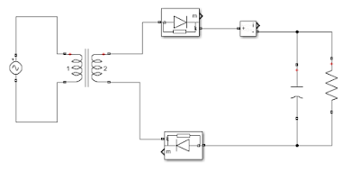
| Center Tapped full wave rectifier |
A center-tapped full-wave rectifier works by using a center-tapped transformer and two diodes to exploit both halves of the AC input cycle. Here's how it operates:
- AC Input and Center-Tapped Transformer: The AC input voltage is fed to the center-tapped transformer. The center tap creates two output terminals, each carrying a half of the input voltage.
- Role of Diodes in Rectification: Two diodes are connected to the transformer outputs. These diodes allow current to flow in one direction only. During the positive half of the AC cycle, one diode conducts, and during the negative half, the other diode conducts.
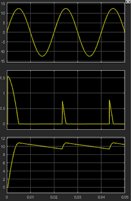
- Output Voltage Waveform: The result is a pulsating DC output voltage that effectively combines both halves of the AC input cycle.
- Filtering and Smoothing: To remove the ripples and obtain a smoother DC output, a filtering capacitor is often added across the load resistor.
- Load Resistor and DC Output Voltage: The load resistor represents the device being powered. The voltage across the load resistor is the rectified and smoothed DC output voltage.
 |
| full-wave rectifier simulation |
Practical Applications of Center-Tapped Full-Wave Rectifiers
Center-tapped full-wave rectifiers find applications in various electronic circuits, including:
- Power Supplies: They are commonly used in power supply circuits for electronic devices.
- Battery Chargers: These rectifiers are used in battery charging circuits.
- Audio Signal Rectification: In audio circuits, they are employed for signal rectification.
- DC Power Generation: When a stable DC voltage is needed from an AC source, center-tapped full-wave rectifiers are a popular choice.
Designing a Center-Tapped Full-Wave Rectifier Circuit
Designing a center-tapped full-wave rectifier circuit involves calculating component values such as the transformer turns ratio, diode selection, capacitor value for filtering, and the load resistor. Here are the essential steps:
- Transformer Turns Ratio: Determine the turns ratio of the center-tapped transformer based on the desired output voltage.
- Diode Selection: Select suitable diodes based on the expected current and voltage ratings.
- Filtering Capacitor: Calculate the capacitor value to achieve the desired output ripple voltage.
- Load Resistor: Choose an appropriate load resistor based on the load requirements and desired output voltage.
Simulation of Center-Tapped Full-Wave Rectifier Using MATLAB
 |
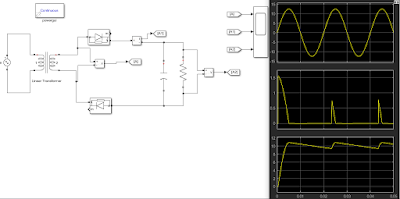
| MATLAB full-wave rectifier circuit |
Now, let's explore how to simulate a center-tapped full-wave rectifier circuit using MATLAB. MATLAB is a powerful tool for simulating and analyzing electronic circuits. Here's a step-by-step summary guide before you watch the video:
- Setting up the MATLAB Environment: Launch MATLAB and create a new script or Simulink model.
- Building the Circuit Model with Two Diodes: Define the circuit components, including the center-tapped transformer, two diodes, filtering capacitor, and load resistor.
- Defining Parameters and Components: Specify the parameters for the AC source, transformer, diodes, capacitor, and load resistor. Set initial conditions as needed.
- Running the Simulation: Execute the simulation and observe the output waveforms.
- Analyzing and Visualizing the Results: Use MATLAB's analysis tools to examine the rectified output, including voltage and current waveforms.
Video Demonstration
For a visual guide on how to design and simulate a center-tapped full-wave rectifier circuit using MATLAB, watch the following video:
Conclusion
In this blog post, we've explored the world of center-tapped full-wave rectifiers, their applications, and the essential components of a center-tapped full-wave rectifier circuit. We've also provided a guide to simulate this circuit using MATLAB, a versatile tool for electronics enthusiasts and engineers.
Understanding and simulating electronic circuits like the center-tapped full-wave rectifier is crucial for anyone working in electronics or related fields. We hope this guide has been informative and helpful in your journey to mastering electronics.
Additional Resources
- [Link to MATLAB's official documentation]
- [Link to our MATLAB Simulink tutorials]
- [Link to our video collection on MATLAB simulation]
Comments and Discussion
We encourage you to share your thoughts, questions, or experiences in the comments section of our social media handles. Feel free to ask for clarifications or share your own insights with the community.


.png)


.png)
.png)